

Simplify a Complex Networking in a Nested Virtualization Using LXD Fan Overlay


Network is a substantial component and key support in the virtualization environment. In the modern application deployment, we use virtualization to manage resources as well as scaling them. However, there are certain cases that we might need a nested virtualization and containerization to manage more complex app and service deployment like doing a containerization inside the virtual machine that runs on a single host or more.
In this article, we will covering the issues in nested networking problem and how to make LXD network management in a nested virtualization. This approach is still applicable in a non LXD Cluster, but in this article we will be covering specifically in the LXD cluster environment.

LXD Virtualization architecture in the picture above shown that we have a single host, that spawning 4 virtual machines that consists of
lxd-1as the LXD cluster nodelxd-2as the LXD cluster nodelxd-3as the LXD cluster nodeload-balanceras the load balancer that need to be accessible through the internet.
They were made to manage the resource that can be used in each workloads. In those setup, we will be using three nodes of LXD cluster in the lxd-1, lxd-2 , and lxd-3 VM. LXD cluster can contains several containers to run app and service inside, to make it visible in the host's neighbor network and the internet through the edge router. This is the basic of the data center architecture looks like.

Let's remind the objective of this article, to simplify the networking inter containers and virtual machine communications. However, the load balancer traffic forwarding to the internet through the edge router will not be covered in this post. Based on the objective, this is the deliverables that needed to be done.
Each container inside the LXD VM should be able to communicate with each others.
Each container inside the LXD VM should be able to communicate with another container from another LXD VM. e.g. container-3 can reach the container 1.
Each running containers should be able to be reached from the load balancer VM.
Each running containers should be able to be discovered from the host machine.
If you have already LXD cluster installed, then you can skip this step and going to the Problem.
Preparation
In this post, we are using Ubuntu 22.04 distribution as it is a common operating system used in the server. The test laptop used is Lenovo Yoga Slim 7 Pro with the detailed specifications are shown here.
| Operating System | Ubuntu 22.04.4 LTS x86_64 |
| Kernel | 6.5.0-21-generic |
| CPU | AMD Ryzen 7 5800HS Creator Edition (16) @ 4.463GHz |
| GPU | NVIDIA GeForce MX450 |
| Memory | 16GB |
Spinning Up Virtual Machines
Ubuntu multipass is used to create lxd-1 , lxd-2 , lxd-3 , and load-balancer VM instances. Each of the instance will have tiny specification, 1 CPU core and 1GB of RAM and 10GB of storage. Of course another VM tools in the market like virtual box, VMWare, Proxmox, Vagrant, or cloud VPS, or even LXC container can be used as well, it doesn't matter.
multipass launch --cpus 1 --memory 1G --disk 10G --name lxd-1
multipass launch --cpus 1 --memory 1G --disk 10G --name lxd-2
multipass launch --cpus 1 --memory 1G --disk 10G --name lxd-3
multipass launch --cpus 1 --memory 1G --disk 10G --name load-balancer
The command above will spawn three virtual machines with 1 CPU core, 1 Gig of memory, and 10 Gigs of storage. To ensure that all of that machine already live, running multipass list command will show all the instances on the host machine.

The terminal above showing that all of the instances already live and ready to be used in the next step.
Forming a LXD Cluster
Starting from lxd-1, we can start to configure the LXD using this command using interactive shell.
lxd-init
When running the command above, it will shows several questions like the images shown here.

Take a careful look we only need this question below to be answered with yes.
Would you like to use LXD clustering? (yes/no) [default=no]:
Afterwards, we can leave any other questions with the LXD defaults configuration. In the default configuration of LXD cluster, they will automatically create a new Fan Overlay Network. This fan network will help us to solve the problem later on.
Before initializing the lxd-2 and lxd-3, we need to generate the join token that will be used when configuring the rest of nodes. Command to generate token would be as follow.
lxc cluster add lxd-2
lxc cluster add lxd-3

Those tokens are used as an authentication that lxd-1 (as the LXD Cluster leader) are permitting another new cluster member joining the cluster.
Joining member will use the same command as initialize the LXD Cluster leader with mandate the sudo command because it will modify system.

While joining cluster, there is interactive shell questions that to be answered before leaving it with the default configurations.
Would you like to use LXD clustering? (yes/no) [default=no]:
yesWhat IP address or DNS name should be used to reach this server? [default=10.79.89.132]:
(leave it blank)Are you joining an existing cluster? (yes/no) [default=no]:
yesDo you have a join token? (yes/no/[token]) [default=no]:
yesPlease provide join token:
(enter the acquired token from lxd-1)All existing data is lost when joining a cluster, continue? (yes/no) [default=no]:
yes
Repeat the command in lxd-3 host. Finally, the LXD cluster are successfully set up. Check whether the LXD Cluster are correctly formed using this command:
lxc cluster list
The command can be called anywhere, either in lxd-1 or lxd-2, or lxd-3 , the result should be showing that all of those host are in the same cluster like the picture below.

The Problem
The problem that we are going to solve is in the networking part, so we may need to revisit the current networking topology after installing the cluster.

The image above shows that the created VM has two IP addresses except for the load-balancer. That is because of the LXD cluster node assign a new interface for its fan overlay network.
TLDR of fan networking;
Fan overlay networking will mask the underlay network (the containers) to the overlay network. As long as we are connected to the overlay network, then we can reach any network available as its underlay network.

The IP address assigned in the lxd-1 instance is coming from lxdfan0 interface that use 240.0.0.0/8 netmask as well as the lxd-2 and lxd-3 has. While initializing the clusters, LXD has managed the networking inside the LXD cluster to be able to communicate and discover the other containers within the cluster. It has been the default network settings for LXD Cluster. Hence, if you are not using the LXD cluster setup, the LXD will use default bridge network.
Let's try to spawn a new container in the any node in the cluster using the command below.
lxc launch ubuntu:22.04 container-1
lxc launch ubuntu:22.04 container-2
lxc launch ubuntu:22.04 container-3
LXD is smart enough to separate the workloads, so the created container will be balanced accordingly based on the free node.

The three containers are up and running and evenly distributed to the LXD cluster node. Now, our network topology with its IP address would be as follow.

With the given conditions, we are having the difference network within the container and the load balancer. Here is the proof that the load balancer are not able to discover the container inside the LXD cluster.
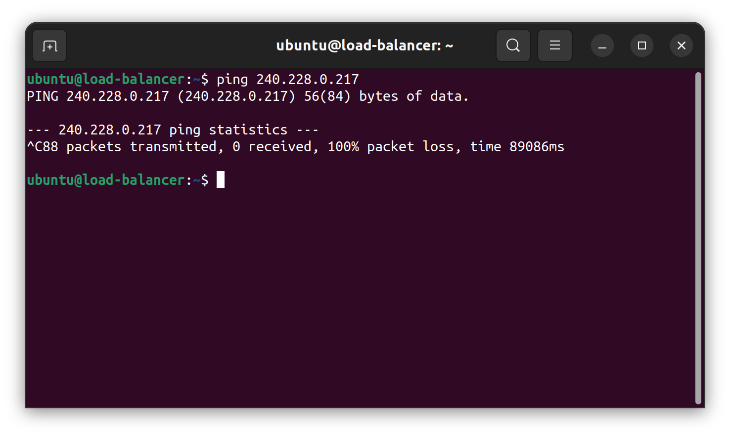
Ping test above showed that the load balancer is not know where the IP 240.228.0.217 are located. In order to make the container available to the load-balancer we need to route the load balancer with the containers. The common way to do this is to append the routing table in the load-balancer instance to one of the LXD cluster because at least one of the instance know where to route to the respected container. The problem using a defined routing is we need to configure the load-balancer and the lxd-* instance to be able to communicate in the both directions.
Solve Using the LXD Cluster Overlay Network
Ubuntu fan networking can easily solve the issues , because adding a new node to join the network is fairly simple and straightforward. The fanctl can be installed by using the ubuntu-fan package in the load-balancer instance.
sudo apt install ubuntu-fan
After the package has been installed, joining a fan network can be done using fanctl as shown in the picture below.

The fanctl up command will register the underlay 10.79.89.225/24 network to the overlay network of 240.0.0.0/8 network. The command before will create two new interfaces that will be used to register the overlay network (fan-240) as a bridge interface and its tunnel interface (ftun0) to route the packet.

Let's try to ping the container again.

It works! Let's try to reverse the other way around.

Voila~ it works 🪄️!!
Apparently, the command above is not persisting the fan-240 config interface. If the system is still using the legacy /etc/network/interfaces config model, then we can use the ifupdown command method as it is explained in the documentation example. However, the Ubuntu 22.04 uses systemd-networkd to configure its host interfaces. Upping interface fan-* requiring executing fanctl command as it is mentioned in the docs, that by default is not supported by systemd-networkd. Another tool that can handle this is the networkd-dispatcher . The complete docs can be accessed in the owner repository.
First, install the networkd-dispatcher package using the command below.
sudo apt install networkd-dispatcher
After completing installation, by default there will be pre-created directories in the /etc/networkd-dispatcher . If the directories doesn't exist, we can create them manually using this command.
sudo mkdir -p /etc/networkd-dispatcher/{routable,dormant,no-carrier,off,carrier,degraded,configuring,configured}.d
Creating a hook script that will be executed when the ens3 interface is up in the load-balancer instance. Create a hook script in the routable.d directory and mark it as an executable. The command would go as follow.
sudo touch /etc/networkd-dispatcher/routable.d/fan.sh
sudo chmod +x /etc/networkd-dispatcher/routable.d/fan.sh
Let's modify the content of the fan.sh using your favorite text editor. In this command, we will be using vim.
sudo vim /etc/networkd-dispatcher/routable.d/fan.sh
The bash script contents can be seen here. Obviously, you need to modify the interface name as my machine use ens3, that can be different on your machine. The fanctl command should be customized as well using the value of your underlying network and overlay network.
#!/bin/bash

if [ "$IFACE" != "ens3" ];
then
    echo "$0: not the interface target, ignoring"
    exit 0
fi

case "$STATE" in
    routable)
        echo "$0: configuring fan network for interface: $IFACE"
        fanctl up -u 10.79.89.225/24 -o 240.0.0.0/8
        ;;
    *)
        echo "$0: nothing to do with $IFACE for \`$STATE'"
        ;;
esac
Restart the instance and the fan-240 interface should be created as well as the ens3 has been configured. To make the host also available in the overlay network, then we just need to do the same things in the load-balancer instance. Restart the instance and see if the fan interface is up with the ens3 interface.
This is a checkpoint on what we have been doing. After setting up the overlay network, we can compare on the complexity problem that exists before.

The picture above is showing that the both the host and the load balancer does not know where to find the specific container inside the LXD Cluster. Registering a new routing table seems to solve the problem, but the directions is only one way not even a roundtrip. For instance, registering a route in the load-balancer to container inside the LXD Cluster through the lxd-3 or lxd-2 or lxd-1, the container-1 still won't be able to reach the load balancer. It will becoming more complex and hard to maintain if we want to add more cluster nodes in the LXD Cluster, or introducing a new workload model like docker container.

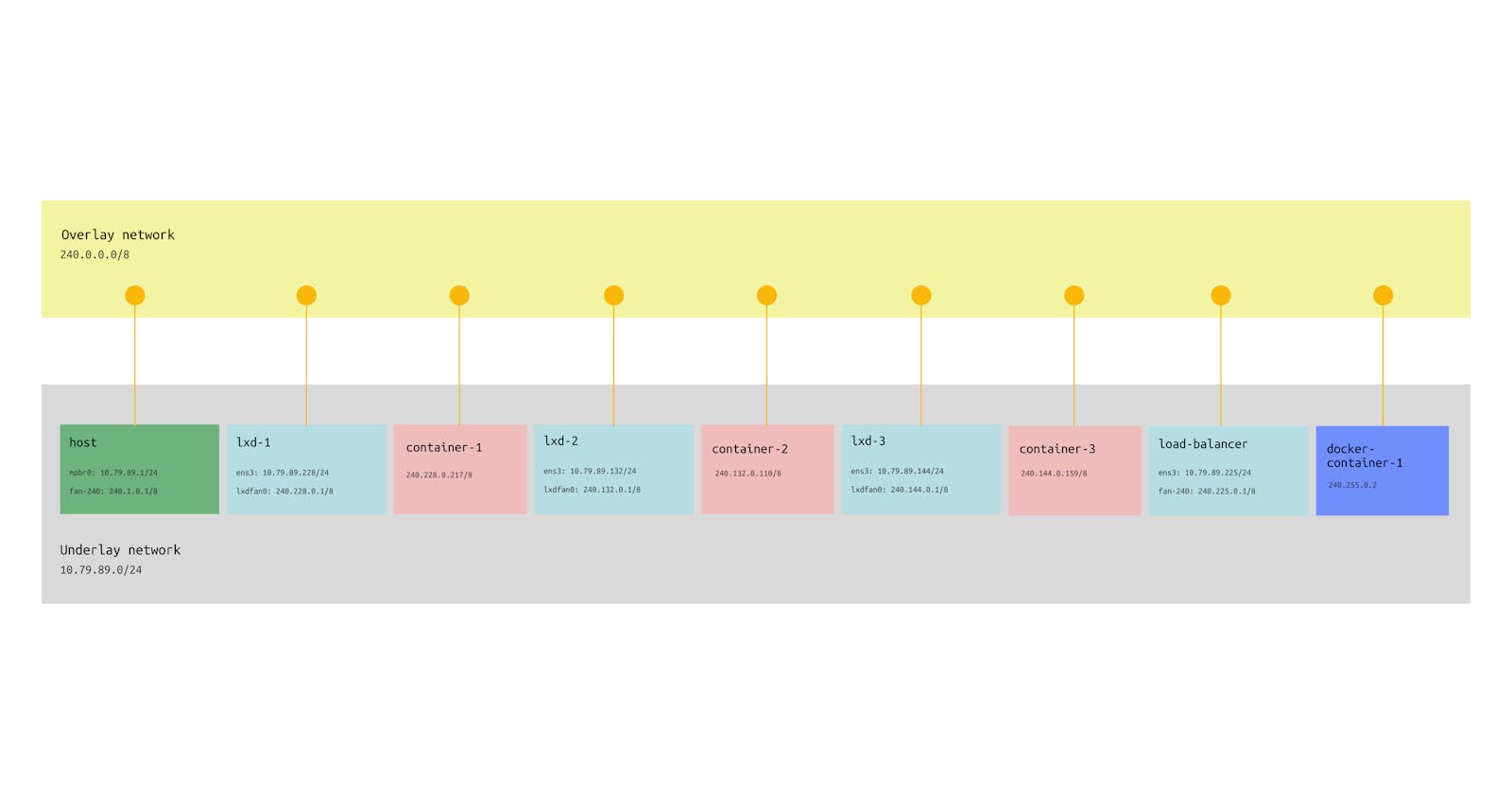
In the picture above, it shows that the network topology are becoming flat. It shows that that we can significantly reduce the network complexity. Each instance can communicate each other easily. Even the host can reach the LXD containers and vice-versa. Now, using the current network topology, we will try to add the docker engine to the overlay network.
Connecting Docker To The Overlay Network
From the previous solution we know that fan networking create a new bridge interface. Thus, by the fan network interface attached, means that we can utilize them even further like adding the docker to the overlay network.
We will try to install docker to the load balancer. We won't cover the installation process, but you can follow the official docker installation instruction here. After the installation succeeded, try to launch a new nginx container with docker-container-1 name.
sudo docker container run -d --name docker-container-1 nginx
By default, the docker-container-1 will use the default bridge network and any instances, even the host (baremetal host) cannot reach it except the load-balancer VM as the docker host. To utilize the fan networking, we can create a new bridge network using the fan-240 interface. In this command, we need to add the subnet as the fan network subnet, the IP range using the host network but sliced in the /24 subnet. Then the gateway address using the load-balancer fan IP address. Last, we need to exclude the unwanted IP range to be used, such as 240.225.0.0.
sudo docker network create --driver bridge \
                      -o "com.docker.network.bridge.name=fan-240" \
                      -o "com.docker.network.driver.mtu=1450" \
                      --subnet=240.0.0.0/8 \
                      --ip-range=240.225.0.0/24 \
                      --gateway=240.225.0.1 \
                      --aux-address="net=240.225.0.0" \
                      fanbr0
After running the command above, we can directly attach the new bridge network to the docker container using the command below.
sudo docker network connect fanbr0 docker-container-1
After running those command, all of the member of the network overlay can communicate to the new nginx container within the load-balancer VM. The IP address of the docker-container-1 can be queried using the docker inspect command and filtering the result using jq (installation required).
sudo docker inspect docker-container-1 | jq '.[0] | .NetworkSettings | .Networks | .fanbr0 | .IPAddress'
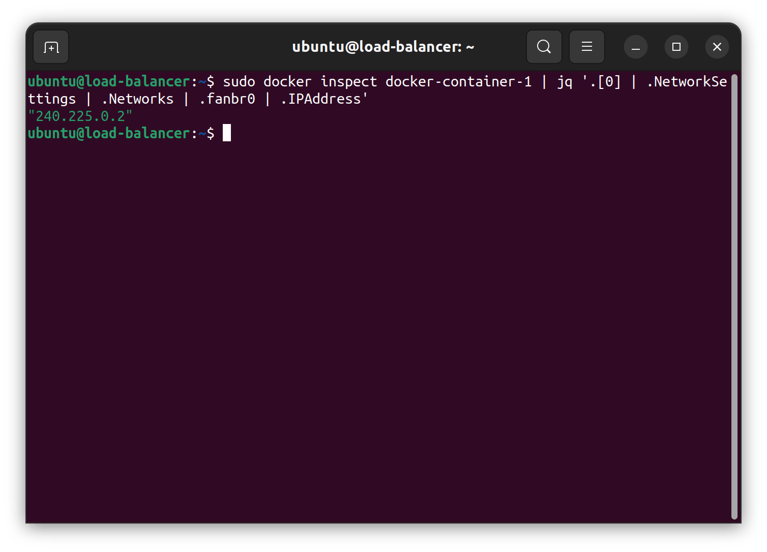
As the image above, the IP adderss of the nginx container is 240.225.0.2 . Here are the test results of ping and curl in the container-2 that is inside the LXD Cluster to the docker-container-1 inside the docker host load-balancer.

That's all. Nice and clean results. Now, let's draw the final network topology again after the overlay network applications and the docker network connection.

As the picture above new docker-container-1 is just appending the flat structure we already built above. Anyone can connect to anywhere as long as they know the IP address inside the overlay network.
Wrap Up
Network management is a one of the key pillar of cloud, virtualization, and containerization environment that plays a big role. The misconfiguration and mismanagement could add more complexity in the long run. The tested environment are forming three nodes virtual machines that spawn a LXD Cluster inside it plus one virtual machine with another containerization workload model such as docker. The test results demonstrate that usage of the overlay network could significantly redact the configuration management complexity in a nested and complex virtualization and containerization environment.